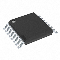
The Texas Instruments TL494CPW is a high-performance integrated pulse-width modulation (PWM) controller designed for use in power regulation applications, including DC-DC converters, power supplies, and inverters. With its robust features and flexibility, the TL494CPW is widely used in applications that require efficient power management and precise voltage control.
## Product Overview
The TL494CPW is a versatile, fixed-frequency PWM controller that operates in various modes, such as voltage-mode control and current-mode control. It is designed to provide precise control of the output voltage and current in switching power supplies, ensuring efficiency in the conversion process. The device integrates multiple control loops and fault detection mechanisms, making it ideal for complex power regulation systems, including isolated and non-isolated designs.
## Key Features
* Adjustable Frequency: The TL494CPW allows users to set the operating frequency between 20 kHz and 100 kHz, providing flexibility for different applications and performance requirements.
* Integrated Error Amplifier: The device features an internal error amplifier, which simplifies the feedback control loop and improves overall power supply regulation accuracy.
* Dual Output Drivers: The TL494CPW is equipped with two output drivers that are capable of sourcing and sinking current, enabling it to drive power MOSFETs directly in both high-side and low-side switching configurations.
* Voltage and Current Mode Control: The TL494CPW supports both voltage-mode and current-mode feedback, offering flexibility in controlling the system's response to load variations and optimizing the transient performance.
* Dead-Time Control: The controller includes dead-time control to prevent shoot-through in the power MOSFETs, enhancing efficiency and reducing losses in the switching process.
* Built-in Protection Features: Integrated overvoltage, overcurrent, and thermal shutdown protections safeguard the circuit against catastrophic failures and ensure long-term reliable operation.
* Error Amplifier Compensation: The internal error amplifier features a wide bandwidth, which is essential for maintaining stable operation in complex power supply designs.
* Low Start-Up Current: The TL494CPW is designed with a low start-up current, making it ideal for energy-efficient applications and minimizing the initial power consumption when turning on the device.
* On-Chip Ramp Generator: The built-in ramp generator simplifies the design process by eliminating the need for external components to generate the required sawtooth waveform for the PWM operation.
## Applications
* Switching Power Supplies: The TL494CPW is commonly used in switching power supplies, both isolated and non-isolated, to regulate voltage and current efficiently.
* DC-DC Converters: The device is ideal for DC-DC converter designs, providing reliable regulation in systems such as point-of-load converters, step-down (buck), step-up (boost), and buck-boost configurations.
* Inverters: It can be used in inverter designs for converting DC voltage to AC voltage, which is commonly used in renewable energy systems and uninterruptible power supplies (UPS).
* Battery-Powered Systems: In applications requiring efficient power management and long battery life, the TL494CPW is suitable for controlling the power conversion stages in battery chargers and power converters.
* LED Drivers: The TL494CPW is used in LED driver circuits, providing constant current control for powering LEDs in a wide range of lighting applications.
* Motor Drives: The controller is employed in motor driver circuits, where precise control of voltage and current is needed to drive motors in applications such as robotics, automotive systems, and industrial automation.
## Electrical Specifications
* Supply Voltage: 7 V to 40 V
* Operating Frequency: 20 kHz to 100 kHz (adjustable)
* Output Voltage: Typically 12 V for the output drivers (depending on the supply voltage)
* Output Current (Source): 200 mA (max) per driver
* Output Current (Sink): 500 mA (max) per driver
* Feedback Input Voltage Range: 0 V to 3 V
* Compensation Pin Voltage: 0 V to 3 V (error amplifier compensation)
* Current Limit: 0.1 V to 1.5 V (external resistor sets current limit)
* Start-Up Current: 10 µA (typical)
* Standby Current: 10 mA (typical)
* Dead-Time Control: 300 ns (typical)
* Thermal Shutdown: 150°C (typical)
* Overvoltage Protection: Active shutdown for overvoltage conditions
* Operating Temperature Range: -40°C to +105°C
## Pin Configuration
The TL494CPW comes in a 16-pin PDIP package with the following pinout:
1. Pin 1 (Vcc): Power supply pin. Connect to the positive supply voltage (7 V to 40 V).
2. Pin 2 (Timing Capacitor): Connects to an external timing capacitor to set the operating frequency.
3. Pin 3 (Error Amplifier Output): Output of the internal error amplifier for feedback purposes.
4. Pin 4 (Ground): Ground reference pin.
5. Pin 5 (Error Amplifier Inverting Input): Inverting input of the internal error amplifier.
6. Pin 6 (Non-inverting Input): Non-inverting input of the error amplifier, typically connected to a voltage reference.
7. Pin 7 (Current Sense Input): Input for current sense feedback, often connected to a current sensing resistor.
8. Pin 8 (Overvoltage Protection): Connects to an overvoltage detection circuit for fault protection.
9. Pin 9 (Output Driver 1): Output driver for controlling the high-side MOSFET.
10. Pin 10 (Dead-Time Control): Controls the dead-time between switching transitions.
11. Pin 11 (Output Driver 2): Output driver for controlling the low-side MOSFET.
12. Pin 12 (Soft Start Capacitor): External capacitor for soft-start function to limit inrush current during power-up.
13. Pin 13 (Compensation Pin): External compensation for error amplifier to stabilize the feedback loop.
14. Pin 14 (Feedback Pin): Connects to the feedback network for regulating the output voltage.
15. Pin 15 (Shutdown/Enable): Logic input for enabling or disabling the output drivers.
16. Pin 16 (Ground): Ground reference for the device.
## Performance and Control Flexibility
The TL494CPW offers excellent flexibility in power supply design due to its wide range of adjustable parameters, including frequency, voltage regulation, and current control. Its ability to operate in both voltage-mode and current-mode control makes it adaptable to a variety of power management applications, allowing it to deliver stable and efficient performance under different load conditions.
The dead-time control ensures that there is no shoot-through current during switching transitions, which maximizes efficiency and reduces losses. Additionally, the built-in error amplifier simplifies the design process by eliminating the need for external op-amps and feedback circuits, thus streamlining the overall circuit layout.
## Reliability and Protection Features
* Thermal Protection: The TL494CPW includes thermal shutdown features to protect against overheating, ensuring that the device operates within safe temperature limits.
* Overvoltage and Overcurrent Protection: The built-in fault detection mechanisms help prevent damage to the system by shutting down the outputs in case of overvoltage or overcurrent conditions.
* Soft Start: The soft-start functionality minimizes inrush current when the power supply is turned on, preventing damage to the components and improving system reliability.
## Conclusion
The Texas Instruments TL494CPW is a powerful and versatile PWM controller designed for use in a wide variety of power regulation applications. Its ability to operate in both voltage-mode and current-mode control, along with integrated protection features, makes it ideal for switching power supplies, DC-DC converters, inverters, and battery management systems. With its adjustable frequency, error amplification, and fault detection capabilities, the TL494CPW provides a reliable and efficient solution for power management in demanding applications.